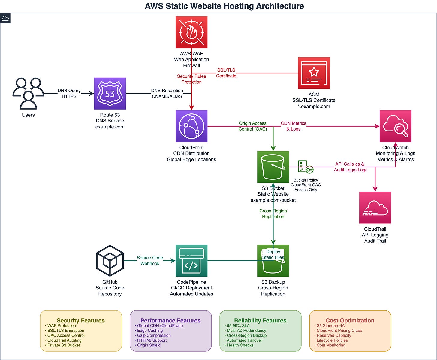
Creating AWS Architecture Diagrams with Amazon Q CLI and Exporting to Draw.io
As cloud engineers, we often need to visualize our AWS architectures for documentation, presentations, or team discussions. While there are many diagramming tools available, Amazon Q CLI offers a unique approach by leveraging AI to generate architectural diagrams directly from text descriptions. In this post, I’ll show you how to harness this capability to create professional AWS architecture diagrams and export them to draw.io for further editing and sharing.
What is Amazon Q CLI?
Amazon Q CLI is an AI-powered command-line tool that extends beyond simple chat interactions. It can understand architectural requirements and generate visual representations of AWS infrastructure, making it an invaluable tool for cloud engineers who want to quickly prototype and document their designs.
Why Export to Draw.io?
Draw.io (now diagrams.net) is a popular, free diagramming tool that offers:
Professional AWS service icons and shapes
Easy sharing and collaboration features
Integration with cloud storage platforms
Export options to various formats (PNG, PDF, SVG)
Version control capabilities
Getting Started with Architecture Diagrams
The key to generating effective architectural diagrams with Amazon Q CLI is crafting clear, detailed prompts that specify:
The AWS services you want to include
How these services connect and interact
The data flow between components
Any specific architectural patterns or best practices
Practical Example: Static Website Hosting on AWS
Let’s walk through creating an architectural diagram for a common use case - hosting a static website on AWS with global content delivery and SSL termination.
The Architecture Components
For a robust static website hosting solution, we’ll include:
Amazon S3 for static file storage
Amazon CloudFront for global content delivery
AWS Certificate Manager for SSL/TLS certificates
Amazon Route 53 for DNS management
AWS WAF for web application firewall protection
The Perfect Prompt
Here’s the exact prompt you should use with Amazon Q CLI to generate this architectural diagram:
Create a detailed AWS architecture diagram for a static website hosting solution on AWS, using S3, CloudFront, ACM, WAF, Route 53 and export it as a draw.io XML file.

Requirements:
1. **Architecture Components:**
 - Include all relevant AWS services: [LIST SPECIFIC SERVICES like EC2, RDS, S3, Lambda, etc.]
 - Show data flow and communication paths between services
 - Include security groups, subnets, and VPC boundaries
 - Add load balancers, auto-scaling groups, and availability zones
 - Show external integrations and third-party services

2. **Diagram Standards:**
 - Use official AWS architecture icons and symbols
 - Follow AWS Well-Architected Framework principles
 - Group related components logically (by tier, function, or AZ)
 - Use consistent color coding and labeling
 - Include network flow arrows with protocols/ports where relevant

3. **Technical Details:**
 - Label each component with instance types, sizes, or configurations
 - Show security boundaries (public/private subnets, security groups)
 - Include backup and disaster recovery components
 - Add monitoring and logging services (CloudWatch, CloudTrail)
 - Show CI/CD pipeline components if applicable

4. **Export Specifications:**
 - Generate as draw.io compatible XML format
 - Ensure all AWS icons are properly referenced
 - Include layer organization for complex diagrams
 - Make it editable with proper grouping and alignment
 - Add metadata for version control and documentation

5. **Additional Context:**
 - Target audience: [Technical team/Stakeholders/Compliance]
 - Complexity level: [High-level overview/Detailed technical/Implementation-ready]
 - Specific compliance requirements: [SOC2/HIPAA/PCI-DSS/etc.]
 - Performance requirements: [Traffic volume/Latency/Throughput]

Please provide the complete draw.io XML code that I can directly import into draw.io or diagrams.net.
Why This Prompt Works
This prompt is effective because it:
Specifies exact services: No ambiguity about which AWS services to include
Defines relationships: Clear connections between services
Includes security considerations: SSL, WAF, and access controls
Requests visual elements: Icons, arrows, and legends
Shows data flow: Step-by-step request path
Step-by-Step: Using the Generated XML
Step 1: Setup Amazon Q CLI
To use Amazon Q CLI you need to download and install it locally:
Run
q loginto authenticateRun
q chatto open a new session
Step 2: Execute the Prompt
Run the prompt above in your Amazon Q CLI session. The AI will provide you with:
Complete draw.io XML code
Architecture design explanation
Component relationship details
Step 3: Copy the XML Output
The response will include XML code similar to this structure:
<mxfile host="app.diagrams.net" modified="..." agent="..." etag="..." version="...">
  <diagram name="AWS Static Website Architecture" id="...">
    <mxGraphModel dx="..." dy="..." grid="1" gridSize="10" ...>
      <!-- Complete diagram structure -->
    </mxGraphModel>
  </diagram>
</mxfile>
Step 4: Import into Draw.io
Open diagrams.net
Click “File” → “Import from” → “Device”
Open the xml file generated
Step 5: Customize and Enhance
Once imported, you can:
Adjust colors and styling to match your brand
Add additional annotations or notes
Include cost estimates or performance metrics
Add deployment or operational details
Export to various formats (PNG, PDF, SVG)
Once you import the file into Draw.io, you will see this architecture
Best Practices for Diagram Generation
Start Simple: Begin with core services and add complexity gradually
Use Standard Terminology: Stick to official AWS service names
Specify Connections: Always describe how services communicate
Include Security: Mention encryption, access controls, and security services
Request Annotations: Ask for labels, legends, and explanatory text
Iterating and Refining
If your first diagram isn’t perfect, you can refine it by asking follow-up questions:
“Add disaster recovery components with cross-region replication”
“Include cost optimization annotations showing Reserved Instances”
“Show the CI/CD pipeline for deploying updates to this architecture”
Conclusion
Amazon Q CLI transforms the way we create AWS architectural diagrams by combining the power of AI with deep AWS knowledge. By crafting detailed, specific prompts, you can generate professional diagrams that accurately represent your cloud infrastructure.
The key is being explicit about your requirements - the more detail you provide about services, connections, and configurations, the better your resulting diagram will be. This approach not only saves time but also ensures consistency across your architectural documentation.
Start experimenting with these prompts and adapt them to your specific use cases. You’ll find that Amazon Q CLI becomes an indispensable tool in your cloud engineering toolkit for both planning new architectures and documenting existing ones.


